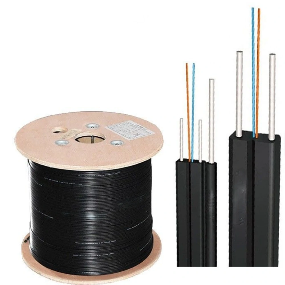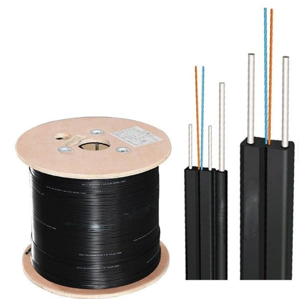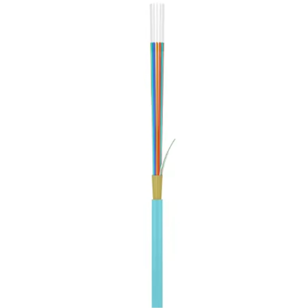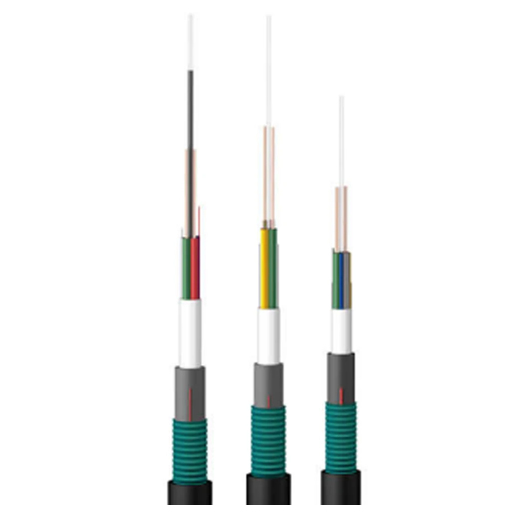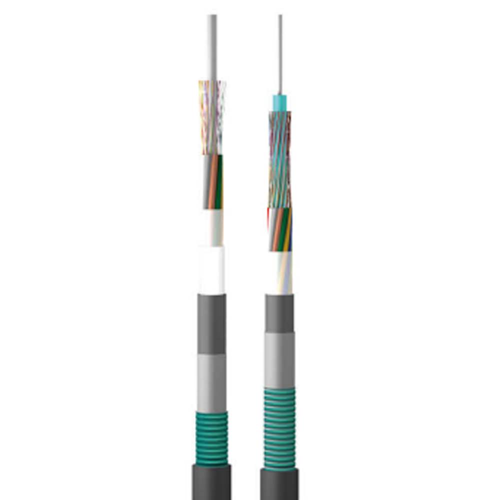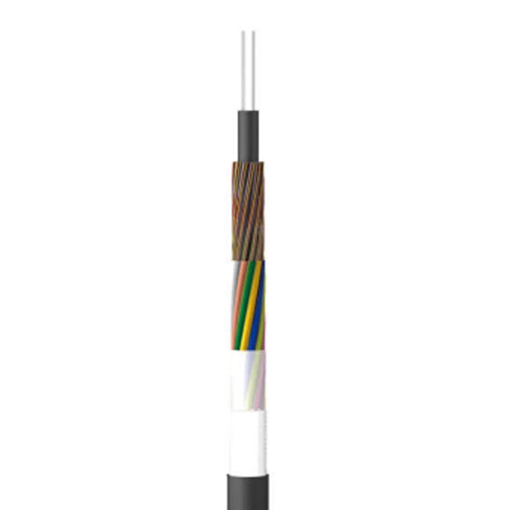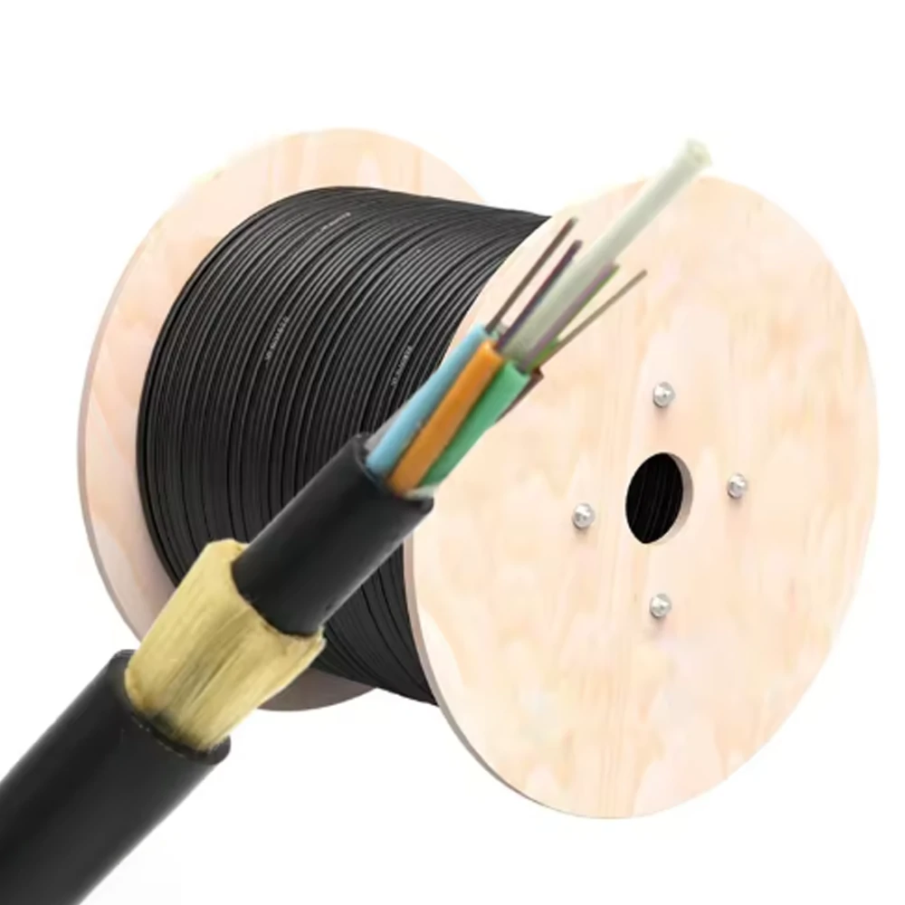
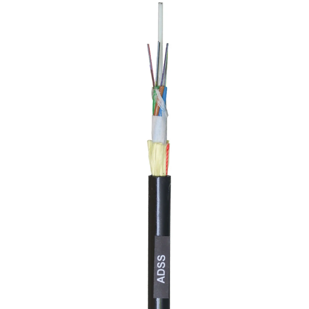
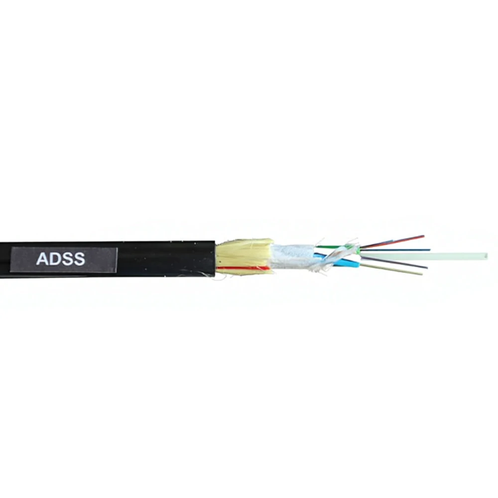
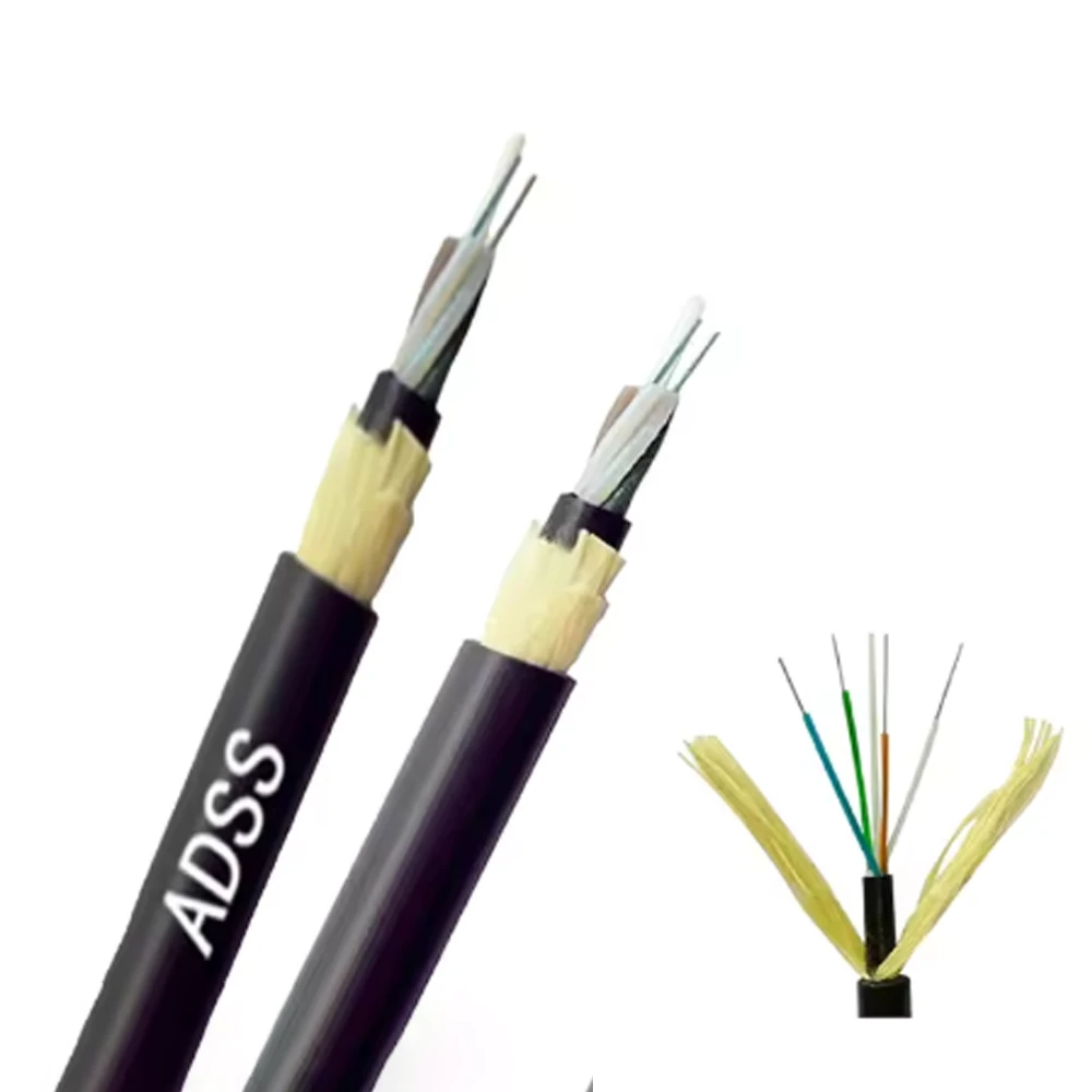
ADSS cable uses a loose-tube stranded construction: 250 μm fibers are placed in high-modulus loose tubes filled with water-blocking compound. Loose tubes (and filler rods) are stranded around a non-metallic central strength member (FRP) into a compact core, with interstices filled with water-blocking jelly. A polyethylene (PE) inner sheath is extruded over the core, followed by aramid yarn strength members, then a polyethylene (PE) or anti-tracking (AT) outer sheath. As an all-dielectric design with no metallic conductive elements, ADSS is suited for self-supporting aerial fiber communications on power-line routes.
Send Message Get Price
| Fiber Type | Attenuation (+20℃) | Bandwidth | Numerical Aperture | Cable Cut-off Wavelength | ||||
| @850nm | @1300nm | @1310nm | @1550nm | @850nm | @1300nm | |||
| G.652 | - | - | ≤0.36 dB/km | ≤0.22 dB/km | - | - | - | ≤1260 nm |
| G.655 | - | - | ≤0.40 dB/km | ≤0.23 dB/km | - | - | - | ≤1450 nm |
| 50/125μm | ≤3.3 dB/km | ≤1.2 dB/km | - | - | ≥500 MHz.km | ≥500 MHz.km | 0.200±0.015 NA | - |
| 62.5/125μm | ≤3.5 dB/km | ≤1.2 dB/km | - | - | ≥200 MHz.km | ≥500 MHz.km | 0.275±0.015 NA | - |
| Reference OD (mm) | Reference Weight (kg/km) | Recommended Max. Daily Working Tension (kN) | Max. Allowable Working Tension (kN) | Breaking Strength (kN) | Strength Member Cross-section (mm²) | Modulus of Elasticity (kN/mm²) | Thermal Expansion Coefficient (×10-6/K) | Suitable Span (m) / Corresponding Weather Conditions | ||||
| PE Outer Sheath | AT Outer Sheath | A | B | C | D | |||||||
| 11.8 | 117 | 124 | 1.5 | 4 | 10 | 4.6 | 7.6 | 1.8 | 160 | 100 | 140 | 100 |
| 12.0 | 121 | 129 | 2.25 | 6 | 15 | 7.6 | 8.3 | 1.5 | 230 | 150 | 200 | 150 |
| 12.3 | 126 | 134 | 3.0 | 8 | 20 | 10.35 | 9.45 | 1.3 | 300 | 200 | 290 | 200 |
| 12.6 | 133 | 141 | 3.6 | 10 | 24 | 13.6 | 10.8 | 1.2 | 370 | 250 | 350 | 250 |
| 12.8 | 138 | 145 | 4.5 | 12 | 30 | 14.3 | 11.8 | 1.0 | 420 | 280 | 400 | 280 |
| 13.1 | 145 | 153 | 5.4 | 15 | 36 | 18.4 | 13.6 | 0.9 | 480 | 320 | 460 | 320 |
| 13.5 | 155 | 163 | 6.75 | 18 | 45 | 22.0 | 16.4 | 0.6 | 570 | 380 | 550 | 380 |
| 13.8 | 163 | 171 | 7.95 | 22 | 53 | 26.4 | 18.0 | 0.3 | 670 | 460 | 650 | 460 |
| 14.4 | 177 | 186 | 9.0 | 26 | 60 | 32.2 | 19.1 | 0.1 | 750 | 530 | 750 | 510 |
| 14.6 | 182 | 191 | 10.5 | 28 | 70 | 33.0 | 19.6 | 0.1 | 800 | 560 | 800 | 560 |
| 14.8 | 195 | 204 | 12.75 | 34 | 85 | 40.0 | 20.1 | 0.1 | 880 | 650 | 880 | 650 |
Note: Specifications are subject to change without prior notice for product improvement. Data Sheet
Can be installed without power outage
AT sheath option with excellent tracking resistance
Light weight and small diameter reduce ice and wind loading on towers and supports
Long spans-maximum span can exceed 1000 m
Excellent tensile performance and temperature characteristics
Expected service life greater than 30 years
It is suitable for various power consumption scenar ios such as residential buildings and commercial office buildings
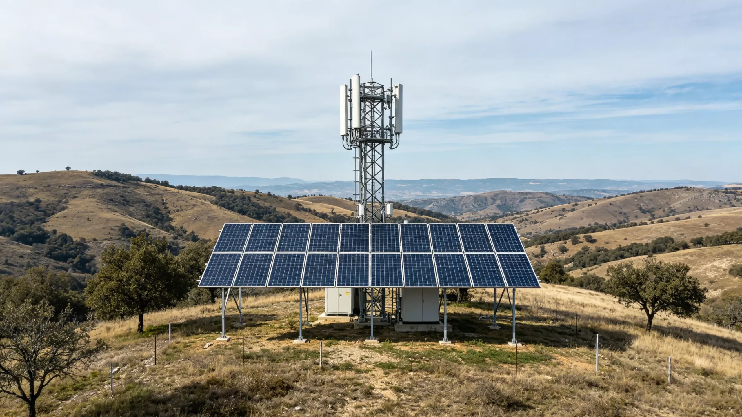
From urban core data centers to remote, off-grid regions, Huijue site power solutions cover a comprehensive range of complex application scenarios worldwide.
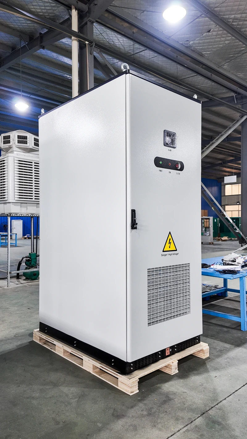
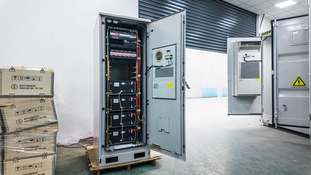
View MoreStandard Site Energy System is an integrated and intelligent core equipment of the telecom power system, widely used in mobile base stations, data centers, and other scenarios. It integrates power supply, power distribution, backup power, protection, and monitoring into one unit, providing stable and reliable -48V DC power and backup battery systems for communication equipment. To cope with the problem of no or difficult grid access for base stations, and in line with the policy trend of energy saving and emission reduction, Huijue Group(HJ Group) has launched an innovative base station energy solution. The solution adopts new energy (wind and diesel energy storage) technology to provide a reliable guarantee for the stable operation of communication base stations. By integrating renewable energy sources such as wind and light energy, with intelligent energy storage system and high efficiency diesel power generation as a supplement, a set of stable, efficient and green energy supply system is constructed, which can satisfy the power demand of telecommunication base stations and help the telecommunication industry to continue to develop stably in the tide of energy saving and emission reduction at the same time.
View MoreCompact Communication Site is an integrated and intelligent core equipment of the telecom power system, widely used in mobile base stations, data centers, and other scenarios.
View MoreIt covers all-scenario power equipment including integrated power supplies, AC-DC converters, outdoor 5G power boxes, indoor/outdoor hybrid energy cabinets, and equipment room power cabinets. It fully supports new energy sources such as PV and wind power, building a hybrid power distribution system of "New Energy + Grid Power + Energy Storage.
View MoreThe Base Station Hybrid Energy Management System is an integrated green power solution specifically designed for telecommunication base stations; by integrating multiple energy sources, intelligent dispatching, and energy efficiency management, it ensures the efficient, stable, and low-carbon operation of base station power supply.
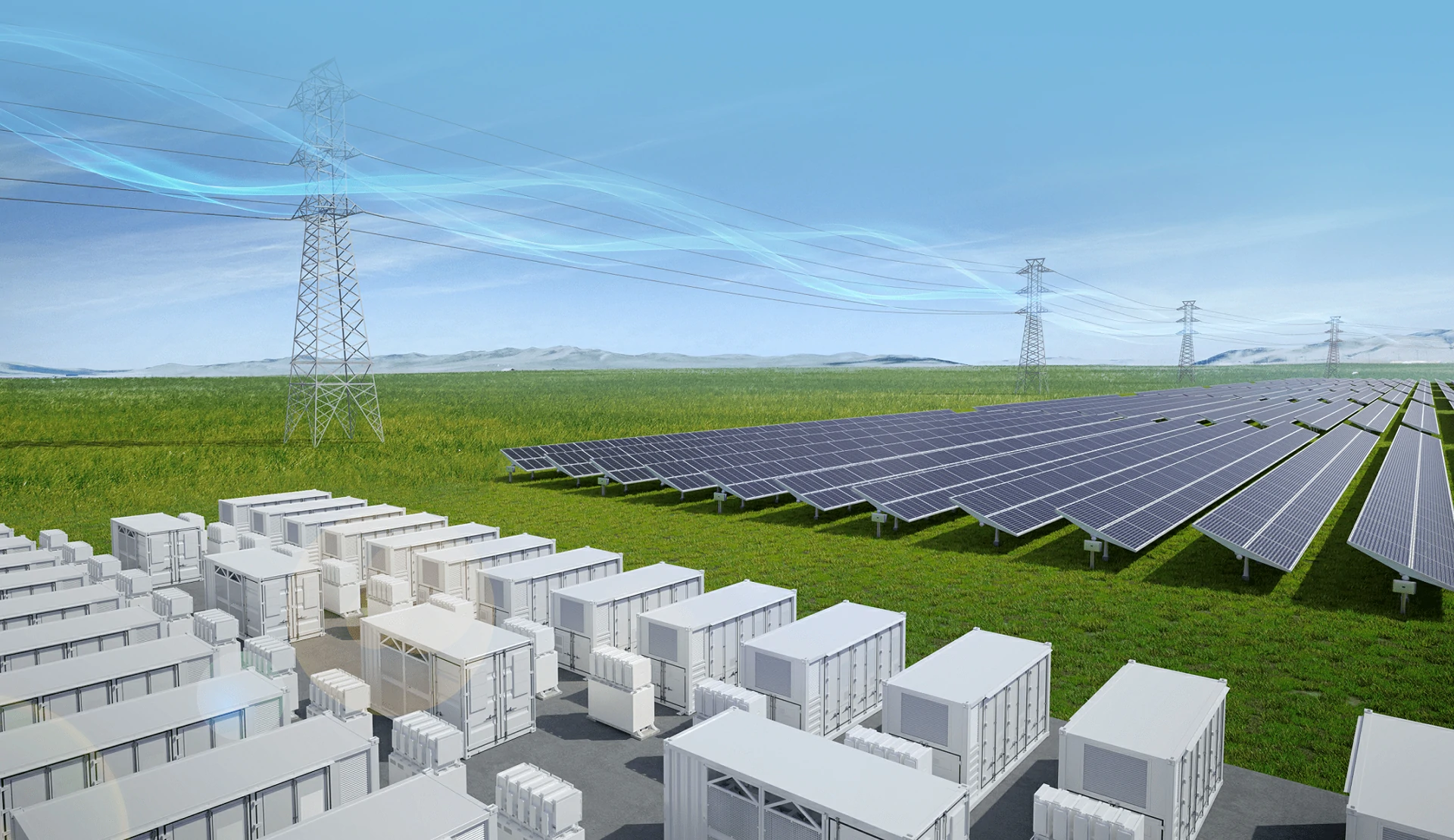
View MoreHuijue Group(HJ Group)'s energy storage solutions (30 kWh to 30 MWh) cover cost management, backup power, and microgrids. HuiJue Group's commercial and industrial energy storage solutions offer capacities ranging from 30 kWh to over 30 MWh. These solutions cover most commercial applications, such as electricity cost management, photovoltaic self-consumption, backup power scenarios, microgrids, and off-grid applications.
View MoreHuijue On-Grid Solution integrates solar, wind, and storage into the grid for efficient power transmission and sustainable energy management. The grid-connected solution by Huijue Group(HJ Group) integrates distributed power sources (such as photovoltaic, wind power, and energy storage systems) into the public power grid. Through grid connection, distributed power sources can achieve efficient power transmission and utilization, providing flexibility and sustainability for energy management.
View MoreWe're committed to providing prompt, professional support to ensure your energy needs are always met with the highest level of service.
We're here to answer your questions and provide the energy solutions that best fit your needs.


 +86 18721624519